- Home
- Technical Products
Enterprise Cloud IT Solutions
Test Measurement
Industrial Measurement
- Solutions
Enterprise Cloud IT Solutions
Test Measurement
- Latest Articles
- About Us
 EN
EN
PCAN-Diag FD:
Handheld CAN/CAN FD Bus Diagnostics
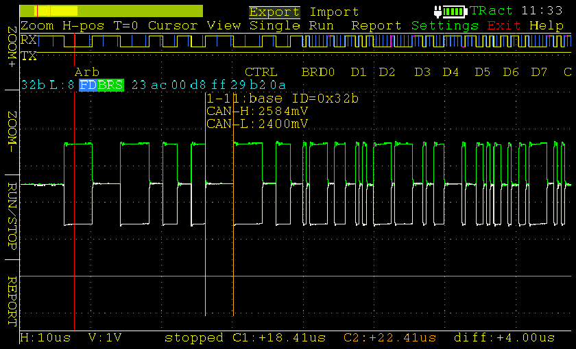
PCAN-Diag FD is a handheld diagnostic tool for CAN bus communication diagnostics. CAN2.0 and CAN FD messages can be diagnosed on a protocol level, and physical layer tests can be performed using the oscilloscope function and the measurement function. The oscilloscope function is used for quality assessment of signal curves on the CAN bus, CAN_H and CAN_L are sampled using separate measurement channels at 100 MHz, and based on the acquired signal curves, PCAN-Diag FD can decode the CAN messages and graphically display the message information.
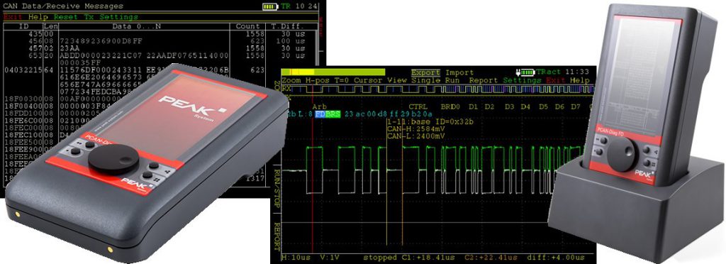
Function Overview:
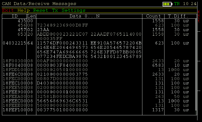
- At the protocol level, the CAN message communication data stream display list can also be loaded with database (e.g. dbc, sym) files to parse hexadecimal messages into specific physical quantities, such as temperature, speed, pressure, etc.
- For further analysis, the Tracer Logging function records CAN messages. PCAN-Diag FD sends CAN messages, either as a single message or as a sequence of messages to the CAN bus; in addition, the recorded CAN messages are also returned to the bus via PCAN-Diag FD. All protocol level functions are available for CAN2.0 and CAN FD.
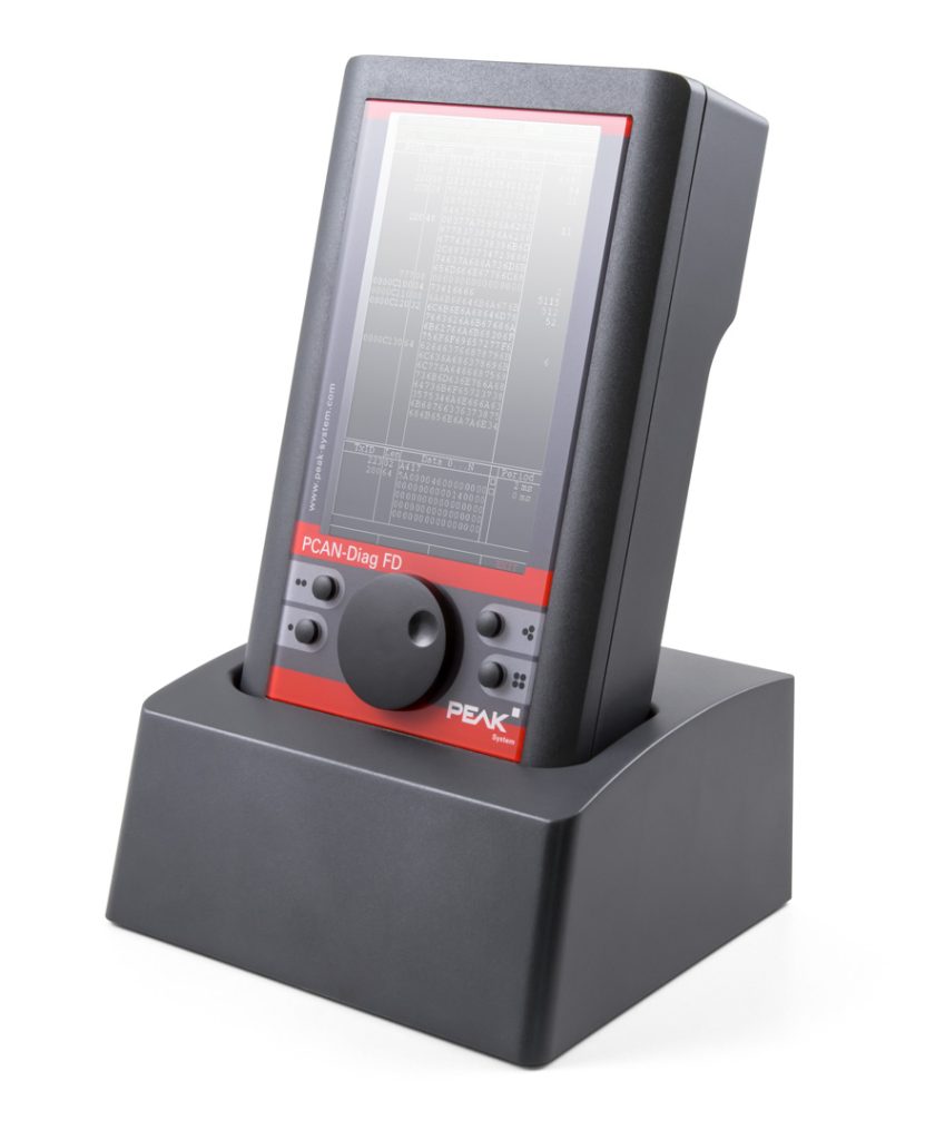
- The main feature of the new CAN FD standard (CAN with Flexible Data Rate) is the higher data transmission bandwidth. Each CAN FD frame can contain up to 64 data bytes (instead of the current 8 bits) and can be transmitted at a bit rate of up to 12 Mbit/s. CAN FD is backward compatible with the CAN 2.0 A/B standard. The PCAN-Diag FD has one pushbutton and four function keys for simple operation. The device can be powered externally or by the internal battery, which is automatically charged when external power is supplied. The charging process can be accelerated by using the optional charging method.
Main Features
- Analyzing CAN and CAN FD networks at the physical and protocol layers
- Select the baud rate from the default list or from a multi-user definition.
- Automatic baud rate detection based on a list of fixed values
- Switchable to listen-only mode
- Selectable silent start function (listen-only mode at incorrect baud rate)
- Symbol parsing file showing the signals of the incoming CAN message, including enumerations (lists of values), multiplexers, and ID ranges.
- Symbol files can be created for parsing CAN telegrams using the included windows software PCAN Symbol Editor.
- Record CAN messages to memory card, CAN ID filter can be used
- Playback of recorded CAN message files
- Recorded files can be converted to ASC or CSV format with Windows® software (PEAK-Converter).
- You can send a single CAN message or a list of CAN messages.
- CAN messages support decimal, hexadecimal, or binary input. The data of a single transmitted message can be changed during runtime.
- Measurement of the CAN bus load, time graph display, switchable display of error frames
- The bus load time graph can be saved as a bitmap screenshot.
- Measurement of the CAN terminals of the high-speed CAN bus is also possible while the system is running.
- Depending on the transceiver module used, the CAN terminals of the connected bus can be switched.
- Measure the voltage of all pins on the CAN connector (D-Sub).
- Manage device configurations, delivery lists, symbol files, and all recorded data (screenshots, traces, and CSV files) in the project
- Automatic repositioning when the bus is turned off
Technical Specifications
- High-speed CAN connection (ISO 11898-2)
- Compatible with CAN2.0A/B and CAN FD standards
- Supports ISO standard and non-ISO standard CAN FD
- Transmission speed of the CAN FD data field (up to 64 bytes) from 20kbit/s to a maximum of 12Mbit/s
- CAN baud rate 20-1 Mbit/s
- Microchip CAN Transceiver MCP2558FD
- Nine-pin D-Sub connector (CiA® 303-1 compliant)
- Screen 800 X 480 pixel resolution
- Vertical or horizontal display according to function and device orientation
- Display on external monitor via micro HDMI connector
- Power supply via internal rechargeable battery or external power supply (low voltage socket)
- Batteries can be recharged from an external power source even during operation.
- Fast charging function available, charging base required (IPEH-003068)
- Internal memory card for project storage and USB mass storage when connected to a computer.
- Operation of the device by one button and four function keys
- Operating temperature: 0-50°C (32-122°F)
Oscilloscope Features
- The oscilloscope contains two independent measurement channels, each with a maximum sample rate of 100MHz.
- Displays the CAN_H and CAN_L signals and also the voltage difference between the two signals.
- Triggering can be configured as
- Frame start and frame end
- CAN Error
- CAN ID
- Baud rate switching for CAN FD frames
- Triggered by external measurement device, using 4mm BNC connector
- Display raw CAN frames and CAN FD frames
- Decode CAN frames and CAN FD frames from recorded signal traces
- The report function displays measurement data for various attributes and decoded CAN frames.
- The current display can be saved as a bitmap.
- Memory depth up to 1M
- Recorded sample data can be saved as a CSV file.
- Extended zoom function
- Time measurement resolution up to 10ns
- Shipping List
Order Number
- PCAN-Diag FD with or without charger, shockproof plastic case
- Configuration software PCAN-Diag FD Editor (Windows®11,10,8.1 (32/64 bit))
- PCAN Symbol Editor for Windows operating system.
- Conversion software PEAK-Converter (Windows®11,10,8.1 (32/64 bit))
- USB cable
- Power supply units are European, US and UK replaceable plugs.
- HDMI/Micro HDMI Cable
- Instruction manual in PDF format
- Quick Start Guide
| Description | No. |
| PCAN-Diag FD | IPEH-003069 |
|---|---|
| PCAN-Diag FD with charging station | ipeh-003069 + ipeh-003068 |
相關產品推薦
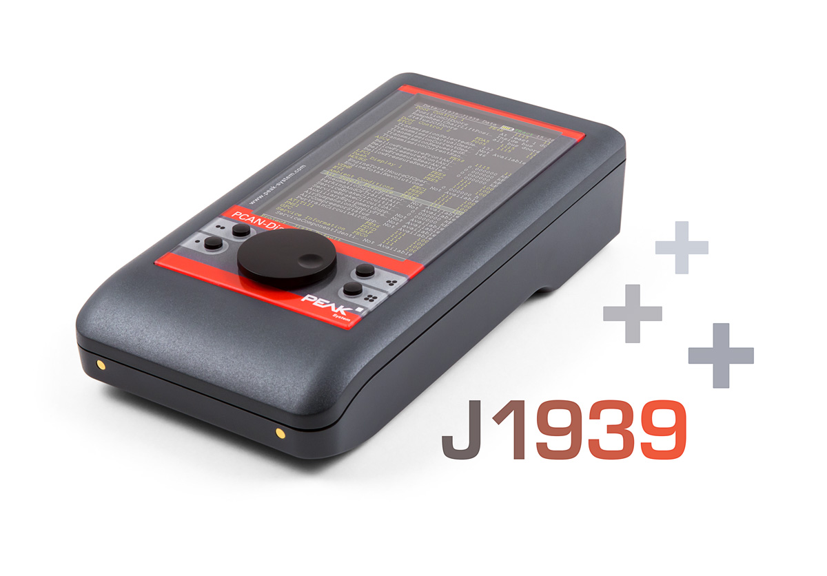
PCAN-Diag FD J1939 擴充插件
PCAN-Diag FD 可選的 J1939 擴充插件
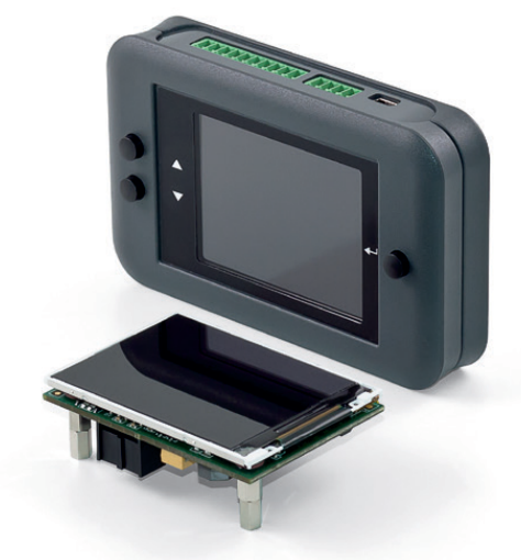
PCAN-miniDisplay
適用於 CAN/CAN FD 匯流排的手持式診斷設備
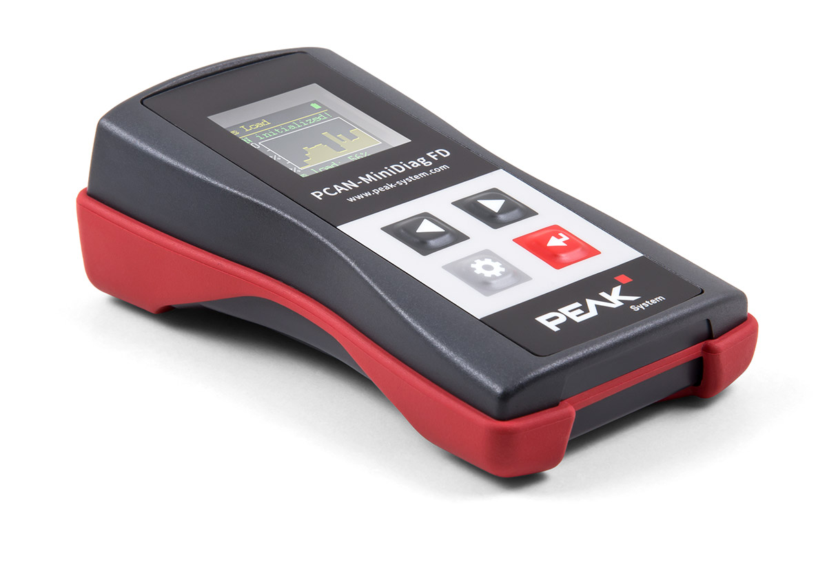
PCAN-MiniDiag FD
手持式 CAN/CAN FD 匯流排診斷儀
Professional technical support from HONGKEI to help you succeed in your project.
HongKe's PCAN-Diag FD is a portable bus diagnostic and test tool that integrates physical layer oscilloscope and protocol layer decoding capabilities designed for on-site diagnostics and bus debugging. Whether it is protocol-layer CAN/CAN FD message capture and decoding or physical-layer signal waveform analysis, PCAN-Diag FD provides intuitive and accurate diagnostic information and operating experience to meet the diverse needs of development, test and maintenance engineers in in-vehicle communication networks.

