
Search

Hongke's latest articles

HongKe

I. Introduction: Strategic Changes at the Data Layer under the Critical Infrastructure Legislation

Add your title text here

[Hongke Case Study] Diagnosis of Poor Acceleration and Timing Deviation in a Chevrolet Cruze

  • Vehicle Information: 2010 Chevrolet Cruze, equipped with an LDE engine, with a total mileage of approximately 150,000 kilometers

  • Core Testing Equipment: Hongke PicoScope Automotive Oscilloscopes, WPS500X Pressure Sensors

  • Fault Symptoms: The engine idles without any noticeable abnormalities, but the engine malfunction light on the dashboard remains on, and the vehicle lacks power when accelerating.

I. Fault Diagnosis and Troubleshooting Process

1. Reading Trouble Codes and Initial Diagnosis

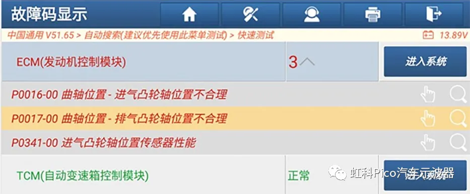
汽車故障診斷儀讀取雪佛蘭科魯茲引擎控制模組(ECM)畫面,顯示儲存 P0016-00、P0017-00 及 P0341-00 三個正時相關故障碼。

After performing a diagnostic check using an automotive diagnostic scanner, it was found that three trouble codes were stored in the Engine Control Module (ECM) (see Figure 1):

  • P0016-00: Inconsistent crankshaft position and intake camshaft position

  • P0017-00: Crank shaft position—exhaust camshaft position is incorrect

  • P0341-00: Abnormal performance of the intake camshaft position sensor

After attempting to clear the trouble codes, although they were successfully cleared, as soon as the engine is restarted,P0016-00 cap (a poem) P0017-00 ...it will be stored again. Based on this, we can tentatively conclude that the cause of the malfunction is closely related to the engine timing system.

(Figure 1: Screenshot of error codes stored in the ECM)

2. Check the oil pressure and check valve

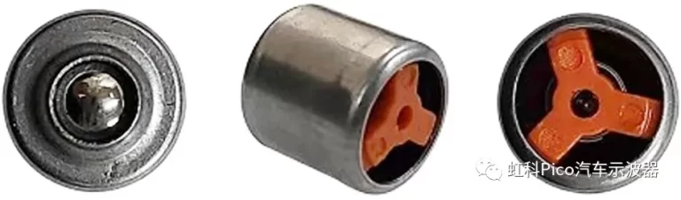
雪佛蘭科魯茲 LDE 引擎機油油路單向閥(止回閥)多角度實物圖,用於排查凸輪軸相位調節器供油壓力異常。

Based on past repair experience, the check valve in the oil circuit of this LDE engine (see Figure 2) is prone to failure due to high engine temperatures, which can lead to insufficient oil pressure. This, in turn, affects the normal operation of the intake and exhaust camshaft phase adjustment actuators, causing the ECM to store P0016-00 cap (a poem) P0017-00 Troubleshooting codes.

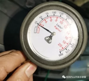
機械式機油壓力錶實測故障車熱機怠速機油壓力約為 180 kPa(1.8 kg/cm²),高於 130 kPa 標準下限,排除油壓不足故障。

The technician then used an oil pressure gauge to measure the engine's oil pressure while the engine was warm and idling; the measured value was approximately 180 kPa(See Figure 3.) The reading is 130 kPa above the lower limit of the standard range, indicating that the oil pressure is normal and ruling out the possibility of a damaged check valve in the oil circuit.

(Figure 2: Check valve in the engine oil circuit)(Figure 3: Measured engine oil pressure in the faulty vehicle while the engine is warm and idling)

3. Analyzing Cylinder Pressure Waveforms Using Hongke PicoScope and WPS500X

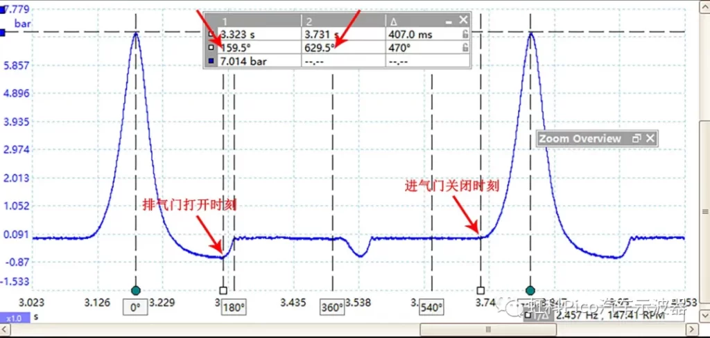
PicoScope 配合 WPS500X 壓力感測器測得的氣缸壓力波形,顯示排氣門開啟(159.5°)與進氣門關閉(629.5°)時刻均過晚。

To further verify the valve timing, the technicians used Hongke PicoScope Automotive Oscilloscope In conjunction with WPS500X Pressure Sensor, measure the cylinder pressure waveform during engine startup (see Figure 4). The analysis results show that:

  • Exhaust Valve Opening Timing: Approximately 20° (180° – 160° = 20°) of crankshaft rotation before the bottom dead center (BDC);

  • Intake Valve Closing Timing: Approximately 90° (630° – 540° = 90°) of crankshaft rotation after the bottom dead center (BDC).

A comparison with the standard valve timing shows that the opening and closing times of this vehicle’s intake and exhaust valves are both significantly delayed.

(Figure 4: Screenshot of the cylinder pressure waveform when the engine of the faulty vehicle is started)

4. Comparison of Engine Timing Waveforms and Calculation of Phase Deviations

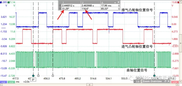
虹科 PicoScope 汽車示波器採集的故障車怠速正時波形,顯示排氣(31.29°)與進氣凸輪軸(116.6°)相位同步延遲約 15°。
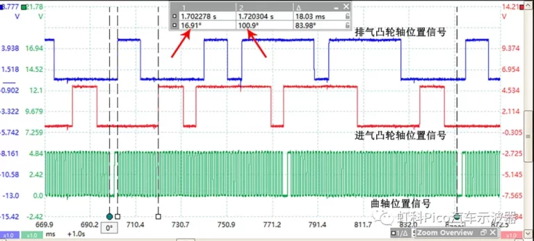
虹科 PicoScope 汽車示波器採集的正常雪佛蘭科魯茲怠速正時組合波形,顯示排氣凸輪軸(16.91°)與進氣凸輪軸(100.9°)標準相位。

Next, disconnect the wiring connectors for the intake and exhaust camshaft phase adjustment solenoid valves, and use Pico Car Oscilloscope Capture the timing combination waveform of the engine at idle (see Figure 5, which shows the synchronized waveforms of the intake and exhaust camshaft position sensors and the crankshaft position sensor), and perform a precise comparison with the normal waveform for the same engine model in the standard timing waveform library (see Figure 6):

  • Exhaust Camshaft Timing Analysis: The time difference between the rising edge of the first narrow tooth signal from the exhaust camshaft position sensor and the falling edge of the large tooth notch signal from the crankshaft position sensor in the faulty vehicle is approximately 31.3° Crankshaft angle; whereas in a normal vehicle, the difference is approximately 17° Crankshaft angle. This indicates that the exhaust camshaft phase on the faulty vehicle is delayed by approximately 14.3° Crankshaft angle (a shift to the right in the waveform indicates a phase delay; a shift to the left indicates a phase advance).

  • Intake Camshaft Timing Analysis: The time difference between the rising edge of the second narrow tooth signal from the intake camshaft position sensor and the falling edge of the large tooth notch signal from the crankshaft position sensor in the faulty vehicle is approximately 116.6° Crankshaft angle; whereas in a normal vehicle, the difference is approximately 100.9° Crankshaft angle. This indicates that the intake camshaft of the faulty vehicle is delayed by approximately 15.7° Crankshaft angle.

Data Diagnostic Conclusions: The intake and exhaust camshaft phases are both delayed by approximately 15° The crankshaft angle—that is, the simultaneous delay in the opening and closing of the intake and exhaust valves—is fully consistent with the conclusions drawn from the analysis of the cylinder pressure waveforms described earlier. Furthermore, a comparison of Figures 5 and 6 reveals that the phase difference between the rising edge of the first narrow tooth on the exhaust camshaft and the rising edge of the second narrow tooth on the intake camshaft is essentially the same for both the faulty and normal vehicles (both being 85° (crankshaft angle, left or right), proving that the relative positions of the intake and exhaust camshafts are correct, and pointing to the root cause of the problem asThere is a deviation in crankshaft timingThe

(Figure 5: Screenshot of the timing waveform from the faulty vehicle's engine at idle)(Figure 6: Screenshot of the timing waveform when a normal vehicle's engine is idling)

5. Disassemble and inspect the timing mechanism to identify the source of the mechanical malfunction

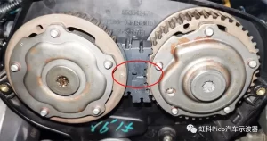
雪佛蘭科魯茲 LDE 引擎進氣與排氣凸輪軸正時齒輪記號校對圖,紅圈顯示雙凸輪軸正時記號對齊正常。
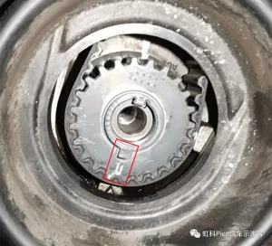
雪佛蘭科魯茲引擎曲軸正時齒輪外部正時記號特寫,紅框顯示外部正時標記表面對齊正常。

After removing the engine timing cover and using a special tool to check the timing, it was found that the timing marks on the intake and exhaust camshafts (see Figure 7) and the crankshaft timing mark (see Figure 8) were all perfectly aligned on the surface. Since the external timing marks appeared normal, and in light of the conclusion regarding “crankshaft timing deviation” precisely pinpointed by the oscilloscope, the technicians strongly suspected an abnormality in the connection between the crankshaft and the crankshaft drive pulley (timing gear).

(Figure 7: Intake and Exhaust Camshaft Timing Marks)(Figure 8: Crankshaft Timing Mark)

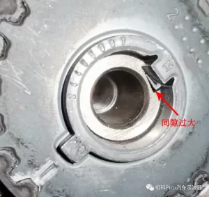
曲軸與曲軸傳動輪連接部位特寫,紅色箭頭標示半圓鍵槽處出現明顯鬆動間隙,引發機械正時偏差。
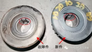
雪佛蘭科魯茲 LDE 引擎曲軸傳動輪故障件與新件對比圖,紅圈標示故障件半圓鍵已嚴重磨損變形,導致曲軸正時偏轉。

The crankshaft and crankshaft pulley in this vehicle are connected via a Woodruff key. Upon careful inspection, significant play was found at the connection point (see Figure 9); after removing the crankshaft pulley, it was confirmed that the Woodruff key was severely worn and deformed (see Figure 10). Due to the damage to the Woodruff key, relative misalignment occurred between the crankshaft and the crankshaft pulley—even though the external timing marks appeared to be aligned, the engine’s actual mechanical timing had deviated by approximately 15°, ultimately causing the check engine light to illuminate and resulting in poor acceleration.

(Figure 9: A noticeable gap is visible at the connection between the crankshaft and the crankshaft pulley.)(Figure 10: Actual photo showing damage to the semicircular key on the crankshaft pulley)

II. Troubleshooting

After replacing the crankshaft pulley and half-moon key with brand-new ones and precisely realigning the engine timing using specialized tools, a road test was conducted: the engine malfunction light on the dashboard no longer illuminated abnormally, the vehicle’s acceleration power returned to normal, and the problem was completely resolved.

III. Four Types of “False Positive” Abnormalities in Non-Invasive Diagnostics

In modern automotive repair, when the following four mechanical abnormalities occur, the ECM will still store fault codes indicating incorrect crankshaft and camshaft positions, even if a visual inspection of the external timing marks shows them to be completely correct. Make good use of Hongke PicoScope Automotive Oscilloscope Combining pressure waveform and timing waveform analysis can help technicians quickly distinguish between genuine and counterfeit parts:.

1. Misalignment between the crankshaft pulley and the crankshaft (as in this case)

This situation affects both the relative positions of the crankshaft and the intake and exhaust camshafts (resulting in a delay or advance in the synchronization of the two shafts), and causes an error in the engine’s actual mechanical timing, leading to abnormalities in both the cylinder pressure waveform and the timing waveform.

2. Misalignment between the intake and exhaust camshaft drive pulleys and the camshafts

If the camshaft drive pulley on one side becomes misaligned, it will affect only the phase relationship between the camshaft and the crankshaft on that side; the phase of the camshaft on the other side will remain normal.

3. The crankshaft position sensor signal disc (target wheel) is misaligned

When this occurs, the engine’s actual mechanical timing remains accurate; it is only the electronic crankshaft position signal received by the ECM that is offset. Therefore, the measuredThe engine timing waveform shows an abnormality, but the cylinder pressure waveform is completely normal.(This allows for a clear distinction from Case 1.)

4. Deflection of the signal disc for the intake and exhaust camshaft position sensors

The principle is similar to that of Case 3; it involves a pure signal-triggered positional offset rather than a mechanical valve timing error. Consequently, while the actual timing waveform shows abnormalities, the cylinder pressure waveform remains normal.

Conclusion

When faced with tricky malfunctions—such as “normal timing signals but phase deviation,” intermittent stalling, or complex sensor signal abnormalities—the traditional troubleshooting method of replacing parts one by one is not only time-consuming and labor-intensive but also increases the risk of misdiagnosis. By Hongke PicoScope Automotive Oscilloscope Pairings WPS500X Pressure Sensor...Technicians can simultaneously capture high-resolution cylinder pressure waveforms and crankshaft/camshaft timing signals without having to disassemble the engine, making hidden mechanical deviations and electronic signal anomalies immediately apparent.

Please feel free to contact Hongke,Inquire about PicoScope automotive oscilloscope solutions and one-on-one technical consultations.

Other Articles

虹科 VST Ensenso C 高精度彩色 3D 相機,架設於自動化包裝與物流傳送帶環境
Hongke Dry Goods

[Hongke Products] Ensenso C High-Precision Color 3D Camera

Discover the Hongke VST Ensenso C compact, high-precision color 3D camera system, which integrates a 2D RGB sensor and a powerful 200W projector, supporting a 5-meter working distance and 0.1-millimeter accuracy at a distance of 1 meter. With its pre-assembled IP65/67-rated design, it effortlessly enables robotic bin picking, logistics palletizing, and AI image analysis.

Read more
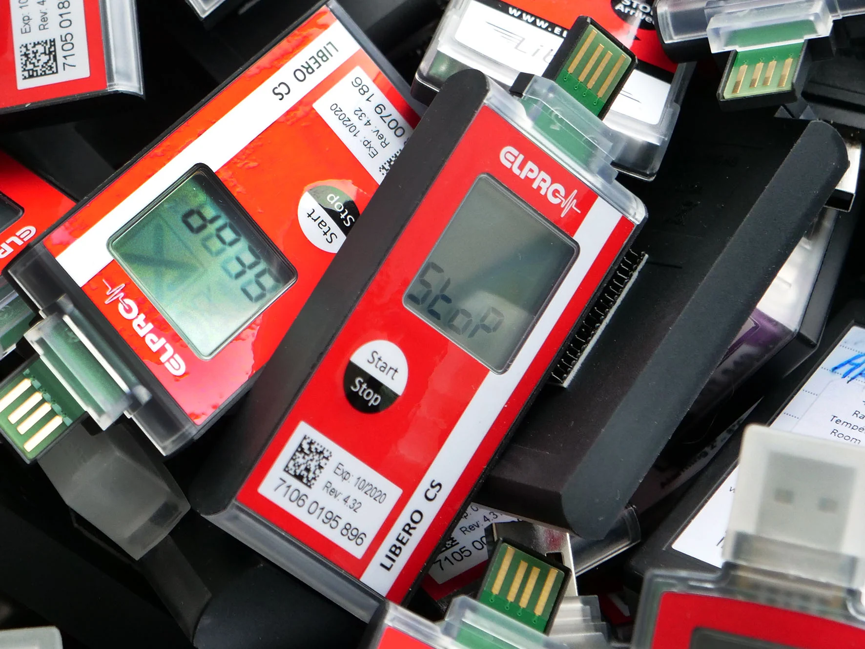
虹科 ELPRO LIBERO CS 一次性 PDF 溫度記錄儀,顯示 LCD 螢幕與 USB 介面特寫
Hongke Case

[Hongke Case Study] Zero-Error Temperature Logging: Cold Chain Compliance Practices for Exporting IVD Reagents

How can companies ensure cold chain compliance and zero-error temperature logging when exporting in vitro diagnostic (IVD) reagents? An analysis of the successful application of Hongke’s LIBERO CS disposable PDF temperature logger in refrigerated transport at 2–8°C. Featuring high precision of ±0.4°C, certification reports for air and sea transport from DGM and the Shanghai Institute of Chemical Industry, and USB data export without the need for software, this solution helps Chinese medical device companies overcome challenges related to overseas compliance and customs clearance. Read the full case study now!

Read more

Contact Hongke to help you solve your problems.

Let's have a chat