
Search

Hongke's latest articles

HongKe

I. Introduction: Strategic Changes at the Data Layer under the Critical Infrastructure Legislation

Add your title text here

[Hongke Case Study] Using the Pico MT03A to Clear BMW Valvetronic Trouble Codes

In modern automotive diagnostics, overreliance on the DTC descriptions provided by scan tools often leads technicians into the trap of “blindly replacing parts.” When the engine control unit (DME) reports an “open circuit,” the actual physical fault may simply be an imbalance in resistance between phases, a safety lockout by the controller, or a floating voltage in the ground circuit.

This article will use a BMW 330e (F30) Equipped with Valvetronic 3 Variable Valve Control System Using this as an example, we'll take a detailed look at how to combine Pico MT03A Milliohm and Motor Tester as well as PicoScope Automotive Oscilloscopes, to perform in-depth logical diagnostics from the physical layer to the signal layer.

Fault Symptoms and Initial Diagnosis (DTC 135808 & 135B11)

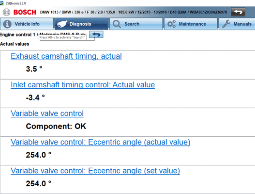
Bosch ESI[tronic] 2.0 汽車診斷軟體數據流畫面:顯示 BMW 330e (F30) Valvetronic 可變氣門控制的偏心軸角度實際值與設定值均固定在 254.0°,證實 DME 已進入失效保護鎖定狀態。
  • Test Models: BMW 330e (F30), equipped with the Valvetronic 3 system.

  • Fault Symptoms: The engine malfunction indicator light (MIL) is on on the dashboard.

  • The diagnostic tool reads the trouble codes::

    • DTC 135808: Fault in the eccentric shaft position sensor's variable valve control function (Position Sensor variable valve control faulty operation).

    • DTC 135B11: Open circuit in the Phase V wiring of the variable valve control drive motor.

💡 Diagnostic Pitfall Alerts: If the DTC 135B11 indicates a “Phase V open circuit,” simply replacing the servo motor or wiring harness will most likely result in a waste of time and money. The DME “infers” the fault based on internal voltage and current feedback, rather than directly measuring the physical circuit.

In-Depth Analysis: How the BMW Valvetronic 3 System Works

The BMW Valvetronic 3 system directly regulates air intake by controlling the intake valve lift, thereby eliminating the need for a conventional throttle valve (which is retained solely for safety purposes and to maintain a slight vacuum in the intake manifold).

  • Enforcer: A three-phase brushless DC motor (3-Phase BLDC Motor) is used to drive the eccentric shaft.

  • Position Feedback Network (5 Hall Sensors)::

    • 3 rotor position sensors: Monitors the position of the motor rotor to ensure precise synchronization of the three-phase power supply.

    • 2 eccentric shaft position sensors: Precisely monitors the rotation angle of the eccentric shaft (with an accuracy of up to 6°) and controls the minimum valve opening to 0.25 mm.

  • Control Core: The motor's high-power three-phase drive and the 5V sensor power supply/ground network are both managed directly by the DME (Digital Engine Management module).

Three-Stage Practical Diagnostic Process

Phase 1: Testing the Valvetronic Motor Windings Using the Pico MT03A

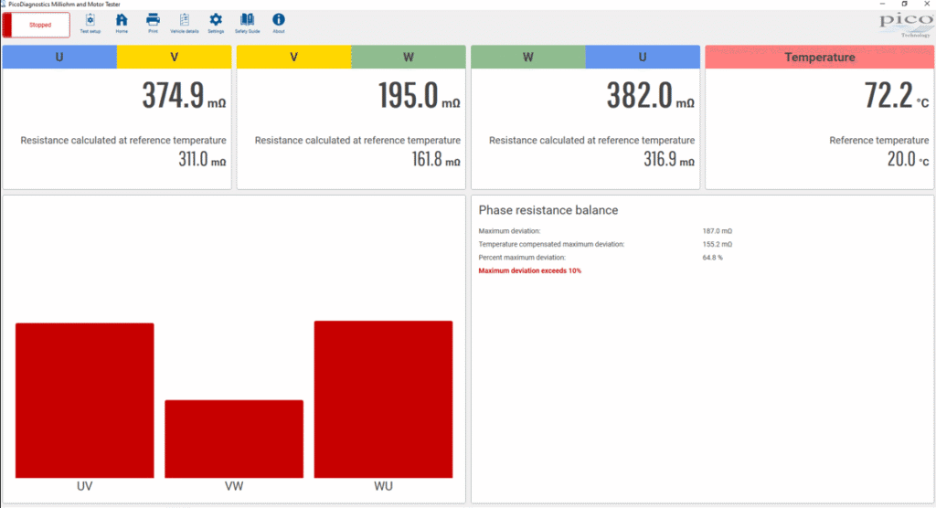
PicoDiagnostics 毫歐與馬達測試儀軟體介面:測量 BMW Valvetronic 三相馬達繞組阻值,顯示 U-V (374.9 mΩ)、V-W (195.0 mΩ) 與 W-U (382.0 mΩ) 存在 187.0 mΩ(64.8%)的嚴重不平衡,遠超 10% 容許上限。

For DTC 135B11 (Phase V Open Circuit), the first step is to perform a physical resistance test on the Valvetronic motor.

  • Limitations of Traditional Multimeters: Because the resistance of BLDC motor windings is extremely low, the resistance between the probes of a conventional multimeter and the contact points can reach several hundred milliohms, which is sufficient to mask actual winding abnormalities.

  • Pico MT03A Milliohm Meter Hands-On Review: Connect the MT03A to the three-phase terminals of the servo motor. The measurement results showThere is a 190 mΩ imbalance in the winding resistance between the three phases., butThere was no actual break in the circuit (open circuit).The

  • Diagnostic Conclusion: The internal windings of the motor are damaged or worn, but the physical connections have not been severed.

Phase 2: Waveform Capture and Data Stream Comparison (PicoScope 4823)

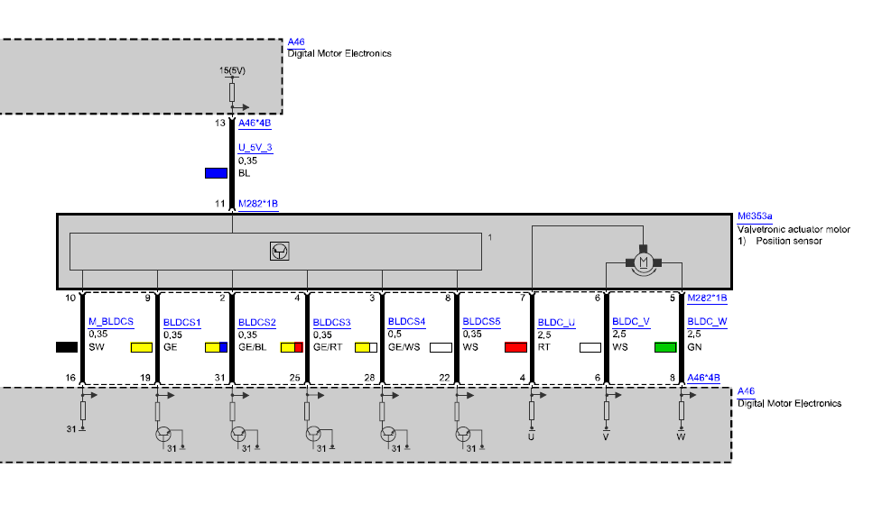
BMW Valvetronic 伺服馬達 (M6353a) 與 DME (A46) 電路圖:展示 5V 傳感器供電、黑色接地線 (M_BLDCS / DME Pin 16)、5 個霍爾效應傳感器信號線,以及三相驅動線路 (BLDC_U, BLDC_V, BLDC_W)。

To investigate DTC 135808 (sensor malfunction), the technician used PicoScope 4823 8-Channel Automotive Oscilloscope Using the ALLDATA circuit diagrams, capture signals from the sensor harness (including wires such as U, B, Y, W, YR, YW, YU, etc.).

  1. Data Flow Analysis: As observed on the diagnostic tool, the control angle output by the DME and the actual angleAll are set to 254°.. This indicates that the DME has entered Fail-Safe Lockout mode and has actively stopped sending motor drive commands.

  2. Grounding Line Abnormality (Floating Voltage)::

    • According to the circuit diagram, the black wire should run through DME Pin 16 Grounding.

    • When measuring with PicoScope, the voltage on that ground wire was surprisingly as high as Approx. 5 V (floating ground)!

  3. Reasons for 5V Floating Ground: When there is a physical break in the ground loop, a loose terminal, or The DME proactively cuts off the internal ground transistor (Ground Gate) to protect itself. In this case, the supply voltage will flow through the sensor network, causing the ground line to drift to the 5V supply potential.

Phase 3: Comparison of Standard Waveforms for Known Good Units (Known Good Baseline)

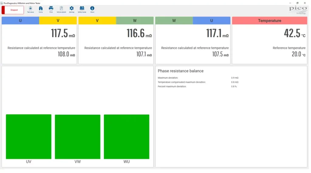
PicoDiagnostics 毫歐與馬達測試儀軟體介面(健康車輛參考波形):顯示 BMW Valvetronic 三相馬達繞組阻值高度平衡,U-V (117.5 mΩ)、V-W (116.6 mΩ) 與 W-U (117.1 mΩ),最大偏差僅 0.9 mΩ (0.8%),柱狀圖呈現正常綠色狀態。

To verify the diagnostic hypothesis, the diagnostic team examined a vehicle of the same model 2019 BMW 320i (B48 engine with Valvetronic 3) The following standard reference waveforms are recorded in the Healthy Vehicle:

  • Rotor Sensor Waveforms: The three rotor position sensors output clear 5V / 0.7V square-wave signals that are perfectly synchronized with the motor's three-phase drive current.

  • Waveform of an Eccentric Shaft Sensor: Two sensors output high-frequency quadrature signals (6 pulses represent one full rotation of the rotor), verifying the relationship between the rotor and the eccentric shaft 10:1 reduction ratioThe

  • Grounding and Resistance Standards: The ground wire of a healthy vehicle always maintains a stable 0V, and the three-phase resistance values measured by the MT03A are highly balanced.

Expert Technical Summary and Maintenance Recommendations

Based on the available diagnostic data, maintenance decisions should follow the following logical hierarchy:

1. Check the grounding circuits first

First, verify the wire continuity and terminal pull force between the sensor and DME Pin 16. If the sensor ground is open, it may trigger both DTC 135808 and 135B11.

2. Retest the motor windings

After restoring the ground connection, use a milliohm meter to measure the motor resistance again. If the 190 mΩ imbalance still exists, the Valvetronic servo motor must be replaced.

3. Expected Outcomes After the Repair

The black ground wire has been restored to 0 V, the resistance of the three phases of the servo motor is balanced, and the eccentric shaft can sweep smoothly between 7.3° and 253.9° without triggering any error codes.

Frequently Asked Questions

Q1: Why does the diagnostic tool display “Open Circuit” when the actual measurement shows only an imbalance in resistance?

A1: The Control Unit (DME) cannot directly measure the physical continuity of the wires; instead, it calculates it using internal current sensors and voltage feedback. When an imbalance in phase winding resistance causes abnormal phase currents, the DME’s logic algorithm may misinterpret the situation and report an “Open Circuit” DTC.

Q2: Why can't a standard digital multimeter be used to test a 3-phase Valvetronic motor?

A2: The resistance of Valvetronic motor windings is extremely low (typically only a few hundred milliohms). The resistance of a standard multimeter’s probes and contact resistance can be as high as 0.1–0.3 Ω, which is sufficient to interfere with the measurement results. Dedicated milliohmmeters (such as the Pico MT03A) use a four-wire (Kelvin) measurement principle, which accurately eliminates probe resistance and precisely measures inter-phase imbalances in the milliohm range.

Q3: What does a 5V voltage on the sensor ground wire indicate?

A3: This indicates an open circuit in the ground loop (floating ground). Possible causes include: ① A physical wire break or a loose pin in the connector; ② Internal damage to the DME module; ③ The DME triggered a protective mechanism and proactively disconnected the internal ground switch to protect the module from high-current surges.

HongKe As Picoauto’s official strategic partner in Greater China, we have long been committed to providing state-of-the-art solutions for automotive aftermarket diagnostics, new energy vehicle maintenance, and industrial testing. PicoScope Automotive Oscilloscopes and MT03A Milliohm Test Solution. Go there nowPicoauto Oscilloscope PageLearn more.

PicoDiagnostics 毫歐與馬達測試儀軟體介面(健康車輛參考波形):顯示 BMW Valvetronic 三相馬達繞組阻值高度平衡,U-V (117.5 mΩ)、V-W (116.6 mΩ) 與 W-U (117.1 mΩ),最大偏差僅 0.9 mΩ (0.8%),柱狀圖呈現正常綠色狀態。
BMW Valvetronic 伺服馬達 (M6353a) 與 DME (A46) 電路圖:展示 5V 傳感器供電、黑色接地線 (M_BLDCS / DME Pin 16)、5 個霍爾效應傳感器信號線,以及三相驅動線路 (BLDC_U, BLDC_V, BLDC_W)。

Other Articles

可配置的CAN FD模擬I/O模塊 功能概述: PCAN-MicroMod FD系列模塊是支持CAN FD的數采模塊。 PCAN-MicroMod FD 插入式板卡可以和即插即用的母板一起購買,母板提供了各種外設可滿足特定需要。對於CAN連接、I/O、和供電,可用彈簧端子連接器。 PCAN-MicroMod FD 數字版1和2著重於數字輸入和輸出,其上有相應的保護電路。數字1的數字輸出裝備了低邊開關,數字2的裝備了高邊開關。
Hongke Dry Goods

[Hongke Solutions] Can’t Read CAN Data? Not Enough Temperature Channels? A Comprehensive Guide to Integrating NVH and Battery Data Acquisition

Is your current NVH data logger unable to read the CAN bus? Are there not enough temperature channels for battery testing? Hongke offers the PCAN-MicroMod FD and MU-Thermocouple1 CAN FD modules to enable CAN(FD)-to-analog conversion and high-density thermocouple multi-module cascading expansion. No coding required—just unbox and use it right away, with no need to replace your existing system!


Read more
Hongke Dry Goods

[Hongke Solutions] AI Agent Implementation Case Study: Enterprise-Level Deployment Across Six Major Industries and the Logic Behind the Underlying Infrastructure

An in-depth analysis of how enterprises can transition from single LLM API calls to autonomous agentic systems. This article compiles real-world examples of AI agent deployments in production environments across six major industries, including retail and finance, and breaks down the underlying infrastructure logic—such as high concurrency, cross-interaction memory (Memory Infrastructure), and distributed state persistence.

Read more
Hongke Dry Goods

HONGKE SOLUTIONS] The Effect of Gaussian Noise on Positioning Effect in GNSS Simulation

In Global Navigation Satellite System (GNSS) radio frequency simulation testing, Gaussian white noise (AWGN) is typically regarded as the baseline configuration for replicating real-world electromagnetic environments. However, engineering practice has shown that the impact of noise on a receiver’s positioning performance does not follow a linear, monotonic relationship. Based on actual measurement data from the DST GNSS simulator, this paper analyzes the physical mechanisms of Gaussian noise in Kalman filters, correlator jitter, and phase-locked loops, and provides a scientific testing guide for configuring simulation noise.

Read more

Contact Hongke to help you solve your problems.

Let's have a chat