
Search

Hongke's latest articles

HongKe

Lorem ipsum dolor sit amet, consectetur adipiscing elit. Ut elit tellus, luctus nec ullamcorper mattis, pulvinar dapibus leo.

Lorem ipsum dolor sit amet, consectetur adipiscing elit. Ut elit tellus, luctus nec ullamcorper mattis, pulvinar dapibus leo.

[Hongke Insights] From “Cables” to “Starry Sky”: Skydel Anechoic Launches a New Paradigm for GNSS Real-World Physical Field Testing

In traditional Global Navigation Satellite System (GNSS) receiver testing, R&D and test engineers typically establish a “closed-loop” conductive connection between the simulator and the receiver using high-frequency RF cables. This traditional conductive testing method has proven highly effective in verifying performance metrics such as receiver sensitivity, satellite acquisition speed, and basic positioning algorithms, and remains one of the most widely used and mainstream standard testing methods in the global navigation and positioning industry today.

However, when dealing with Controlled Reception Pattern Antenna (CRPA) arrays that require spatial filtering to eliminate external interference sources, or in operating conditions where the installation environment—such as reflections from the aircraft fuselage surface, physical distortion of the antenna radome, conventional direct cable connection solutions prove inadequate and are fundamentally incapable of accurately reproducing the true, complex spatial physical field environment. How can we utilize anechoic chamber technology—commonly known in the industry as “starry sky” multi-antenna radiation testing—in a controlled laboratory setting to to precisely reconstruct the three-dimensional spatial geometry and phase relationships between satellite signals and interference sources, and to perform real-time closed-loop verification of the physical coupling and phase characteristics among antenna elements, has become a new core challenge in the field of high-precision navigation testing. In particular, with the rapid rise of the low-altitude economy (such as unmanned aerial vehicles (UAVs) and electric vertical takeoff and landing (eVTOL) aircraft) in Hong Kong and Southeast Asia in recent years, the industry has placed significant emphasis on physical field simulation technologies for such extreme environments.

In addition to providing standard GNSS simulator solutions, Hongke has collaborated closely with leading global partners to launch a brand-new, high-precision test system designed for simulating real-world GNSS environments and precise phase angles— Skydel Anechoic Simulation SystemThe

What is an anechoic chamber radiation simulation system?

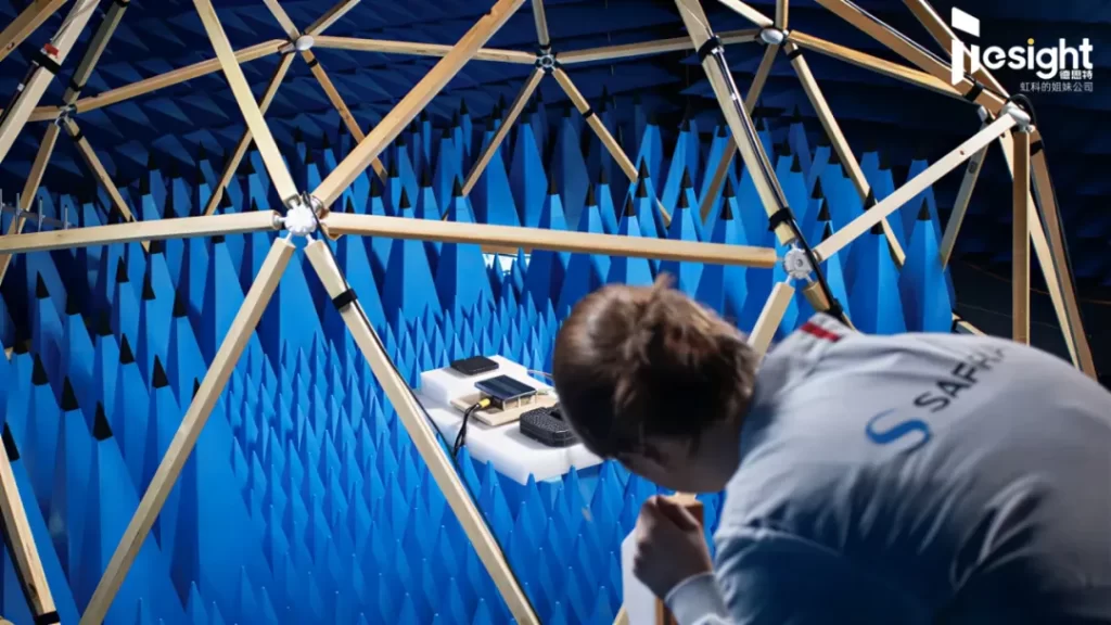
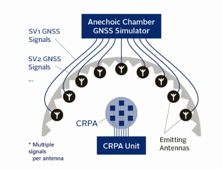
Skydel Anechoic This is an advanced GNSS radio frequency space simulation system designed to “perfectly replicate a three-dimensional sky” in a controlled indoor environment. It completely overcomes the physical limitations of traditional cable connections, by scientifically deploying a transmitter antenna array (Tx Array) in a professional microwave anechoic chamber, it realistically projects and transmits high-fidelity simulated satellite signals to the device under test (DUT) via over-the-air (OTA) transmission.

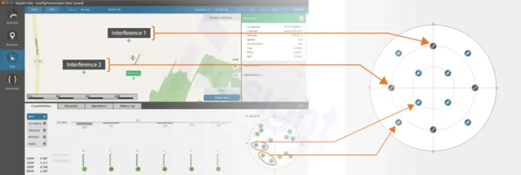
This system not only accurately represents, at the physical level, the precise angle of arrival (AoA) of each navigation satellite and complex interference sources, but also requires the simulated signals to realistically penetrate the protective antenna radome or bypass the complex airframe structure. This advanced “Wavefront Reconstruction Technology” enables the CRPA array’s spatial filtering and anti-interference capabilities, as well as the signal phase distortion caused by physical obstruction from the airframe, to be precisely captured and verified in the laboratory—just as they would be in the real-world airspace tens of thousands of miles above the ground.

Core Applications of Anechoic Chambers

  • CRPA Immunity Limit Test: Test controlled reception pattern array (CRPA) antennas on high-value unmanned aerial vehicles (UAVs) or special-purpose vehicles. Thoroughly verify whether, when subjected to interference sources from different directions and at different frequencies, these antennas can physically and precisely “shield” the interference incidence angles using beamforming technology.

  • Testing for Obstruction by the Antenna Radome and Airframe Structure: Test GNSS antennas installed inside aircraft fuselages, drone skins, or high-specification antenna radomes to verify the effects of physical structures and material refraction on dynamic signal phase and gain distortion.

  • High-Precision OTA (Out-of-Band Testing): Comprehensively verify the phase center stability of smartphones, smart wearable devices, high-precision measurement antennas, or drones (including phase center offset (PCO) and phase center variation (PCV)). These micrometer-level physical parameters cannot be detected or measured using traditional cable testing methods.

  • Protection Against Spoofed and Deceptive Signals: In a simulated complex electronic warfare/signal countermeasures environment, test the receiver’s ability to accurately identify and filter out spoofing signals by determining the angle of arrival (AoA) of spatial signals.

New Anechoic Solution Architecture — Integrated Hardware and Software Design

complete Skydel Anechoic System Seamlessly integrated from the following precision components, which combine hardware and software and complement each other’s strengths:

  • Skydel Software Engine: Responsible for calculating and outputting, in real time and with ultra-high concurrency, satellite orbits for multiple navigation constellations, mathematical models of complex interference sources, and the highly dynamic trajectories and attitudes of spacecraft;

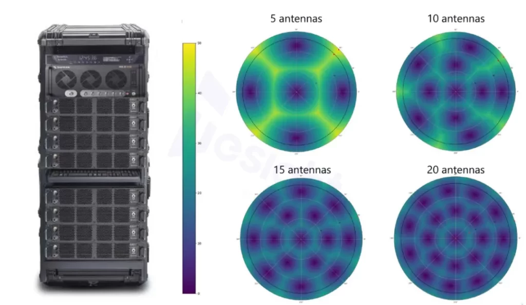
  • The Latest Generation of GNSS Simulators: The GSG Product Suite: Based on a leading commercial off-the-shelf (COTS) hardware architecture, it flexibly provides up to 21 or more fully independent RF physical outputs;

  • High-Precision Time and Clock Distribution System: By leveraging a high-precision clock source and a clock distribution network, it ensures that every RF signal transmitted by the GNSS remains highly synchronized at the picosecond level;

  • Transmit Antenna Array (Tx Array): Transmitter antennas precisely positioned around the perimeter of the anechoic chamber represent different three-dimensional geometric orientations and can flexibly support up to 21 “Sky Satellites”;

  • Automated Calibration Tool: The system’s core algorithm fully and automatically compensates for the delay and power loss that occur throughout the entire path—from the signal’s origin at the simulator, through complex cabling, and via air—until it reaches the device under test (DUT), without any manual intervention.

What does this solution offer?

  • Full System Closed-loop: Incorporate “physical antenna + RF front-end + baseband signal processing + positioning algorithm” into a single real-time HIL test loop;

  • Rapid Calibration: By significantly reducing the time required for dark-room phase calibration—a process that was originally extremely complex and often took several days—to just “a few minutes” and automating it, the testing throughput and development efficiency of R&D laboratories have been greatly improved;

  • Industry-leading fully automated technology: Full support for automatic antenna mapping, automatic cable and air-interface delay calibration, and automatic path power loss compensation;

  • A "turnkey" solution that's ready to use right out of the box: A turnkey product that can be deployed directly in a large, fixed microwave anechoic chamber or flexibly integrated into a multifunctional, portable anechoic chamber.

How to Choose the Most Suitable GNSS Test Solution for Your Application?

Given different R&D stages, technical requirements, and the scale of antenna testing, how should the optimal test path be planned when using conventional GNSS simulators and high-end anechoic systems?

  • GSG-7C: A highly integrated, standard-type multi-frequency, multi-constellation GNSS simulator.

  • GSG-8 Gen2: A high-end GNSS simulator that supports high-concurrency real-time simulation across multiple channels and scenarios.

For most scenarios involving the development, algorithm debugging, and consistency verification of positioning and navigation systems, choose the standard GSG Series GNSS Simulators It remains the mainstream, cost-effective solution of choice. Its core strengths lie in its exceptional flexibility and configurability; thanks to powerful software algorithms, standard conductive simulation is sufficient to perfectly cover the vast majority of routine testing needs, ranging from basic positioning to highly dynamic trajectories.

However, when your application scenario is extremely sensitive to carrier phase shifts and changes in angle of arrival (AoA)—such as in unmanned vehicles or eVTOLs—or involves highly precise antenna physical field simulations, physical interference immunity verification of CRPA arrays, and the pursuit of the highest testing standards,Hongke Skydel Anechoic System It will provide the most robust foundation for real-world physics verification—one that meets the highest international aerospace standards—for your space-based systems and physical interactions.

Other Articles

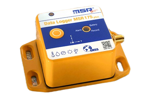
虹科 MSR175plus 衝擊與環境數據記錄器外觀圖:黃色堅固外殼配有 GNSS 定位功能、三軸加速度(X/Y/Z)以及溫度、濕度、氣壓、光照與傾斜感測器圖示,專用於運輸與物流監測。
Hongke Dry Goods

[Hongke Case Study] TSMC Selects MSR Shock and Vibration Data Loggers

How Can You Prevent Vibration Damage During International Transport of Semiconductor Wafers and Photomasks? We Reveal the Key Reasons TSMC Chose Hongke’s MSR175Plus Shock and Vibration Data Logger! The product features long battery life and large-capacity memory, enabling precise recording of temperature, humidity, pressure, and multi-axis acceleration during long-distance transport. In an exclusive interview, a TSMC engineer shares how the company converts vibration into quantifiable data and establishes rigorous standards to effectively reduce the risk of damage and significantly improve the success rate of international shipments!
Read more
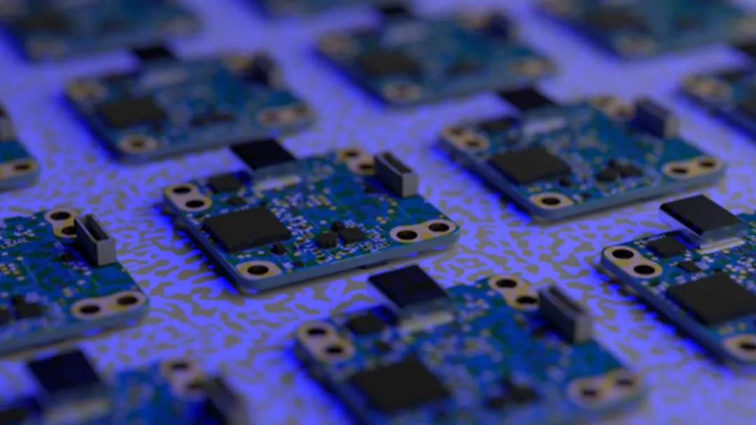
PCB 電路板組裝視覺檢測與測量示意圖:陣列排列的印刷電路板(PCBA)在藍光光源下展示晶片、元件與金屬焊盤細節,適用於 SMT 表面貼裝自動光學檢測(AOI)與品質管控。
Hongke Dry Goods

[Hongke Solutions] How Can AI-Powered Industrial Vision Inspection Overcome Quality Bottlenecks? A Comprehensive Analysis of Multi-Camera PTP Synchronization and Defect Detection

An In-Depth Analysis of AI Industrial Vision Inspection Technology! Explore how high-resolution industrial cameras, AI deep learning algorithms, and IEEE 1588 PTP microsecond-level multi-camera time synchronization precisely overcome bottlenecks in PCB component measurement and lithium-ion battery defect detection, and SMT Automated Optical Inspection (AOI), thereby improving production line yield!

Read more
可配置的CAN FD模擬I/O模塊 功能概述: PCAN-MicroMod FD系列模塊是支持CAN FD的數采模塊。 PCAN-MicroMod FD 插入式板卡可以和即插即用的母板一起購買,母板提供了各種外設可滿足特定需要。對於CAN連接、I/O、和供電,可用彈簧端子連接器。 PCAN-MicroMod FD 數字版1和2著重於數字輸入和輸出,其上有相應的保護電路。數字1的數字輸出裝備了低邊開關,數字2的裝備了高邊開關。
Hongke Dry Goods

[Hongke Solutions] Can’t Read CAN Data? Not Enough Temperature Channels? A Comprehensive Guide to Integrating NVH and Battery Data Acquisition

Is your current NVH data logger unable to read the CAN bus? Are there not enough temperature channels for battery testing? Hongke offers the PCAN-MicroMod FD and MU-Thermocouple1 CAN FD modules to enable CAN(FD)-to-analog conversion and high-density thermocouple multi-module cascading expansion. No coding required—just unbox and use it right away, with no need to replace your existing system!

Read more

Contact Hongke to help you solve your problems.

Let's have a chat